2D with Depth
Out of interest, I searched the net on how those people from Obsidian made that great graphics for Pillars of Eternity.
According to this (and other sources), they compose the backgrounds in a 3D modelling program, then create a pre-rendered picture with depth information export, then combine all this (and more) in Unity3D with ‘real’ 3D objects (avatars and alike). That way, they don’t need to import large 3D scenes (with many objects to render) into the game engine, thus reducing the overall load.
Now, I wondered how this approach could work using my currently preferred tool pipeline, which consists of C4D and Unity3D. Below, I’m elaborating on the different steps it took to create a “demo” that finally shows the concept (all source files are also available for download).
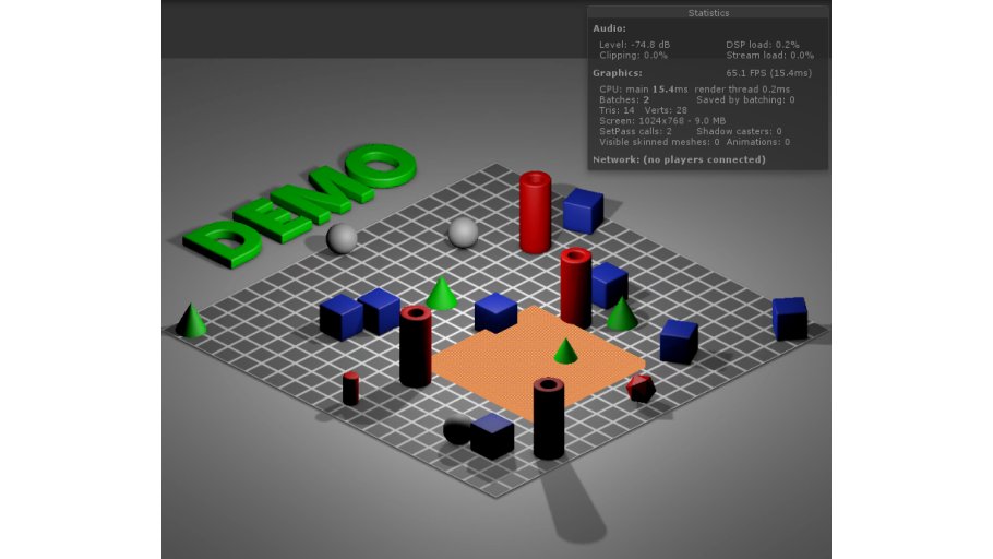
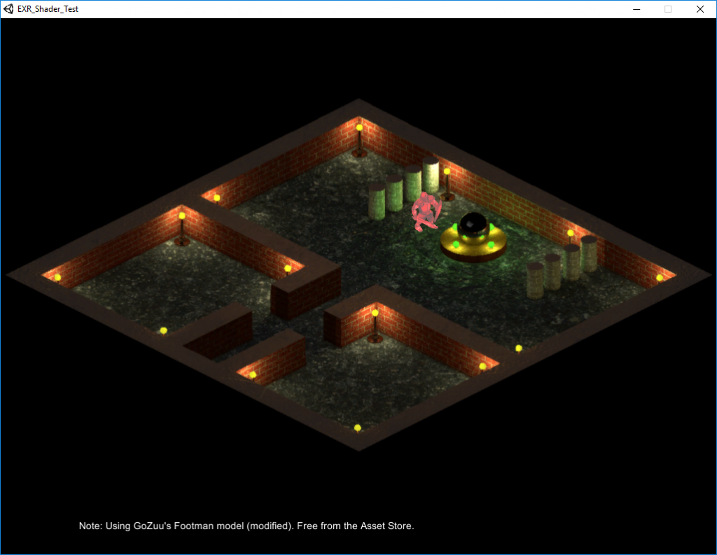
Please see the screenshot above. Lots of objects in there, right? Uhm, no. Actually, there are only two 3D objects present in the scene: The orange flat cube (which can be moved around), and a quad that holds the pre-rendered background image with all those tubes and cones and whatnot.
As you can see, the ‘perspective is still ok’, though – well, as good as it can get for an isometric view 😉 . Some parts of the orange thingy are hidden by ‘objects in sightline’, while the orange cube itself covers parts of the scene that lie underneath it. That effect was achieved by using C4D’s PositionPass export feature and a custom shader in Unity.
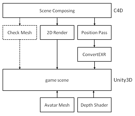
The rough work flow can also be seen here:
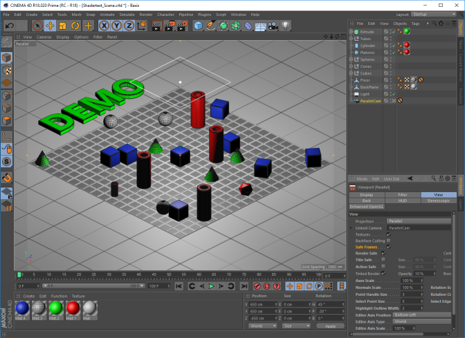
C4D Scene Composing
To be able to ‘sync’ the pre-render picture and data with objects in real 3D later, some boundaries must be considered. Here is what I did:
- Use a ParallelCamera and position at 650/650/-650 cm, rotation at 45/-30/0 deg.
- Always use a large ‘background plane’ that covers the whole camera space, to avoid ’empty areas’.
- Zoom in Camera until all objects gently fit into the available view space (better activate ‘Safe Frame’ View).
- In Render Settings, activate ‘Multi-Pass Post Effects’ and ‘Position-Pass’, set Position-Pass properties to ‘World, RGB, Scale 1 and to not Invert Z.
- Set output file names for Rendering (*.png) and Pass (OpenEXR 32bit). I used a picture size of 1024×768.
Pre-Render Scene, Export and Convert Position Pass
When rendering the scene in C4D (Shift-R), two files should now be created. The pre-render picture (*.png), and the position pass output (*.exr). The latter one contains information about each pixel’s position in space (i.e., what 3D world position of the scene this pixel was generated from).
Btw(1): Information about the OpenEXR format can be found here: http://www.openexr.com/
Btw(2): For viewing such files, I used RenderDoc (https://github.com/baldurk/renderdoc).
Later, in Unity, the position pass data will be stored to a RGBFloat texture and be used in the custom shader.
As I had problems when directly importing the *.exr into Unity, I used a small tool to convert the data into *.txt and *.bin (only one type is needed later). Check here for the tool.
Note that position data is normalized to [0..1] before storing it to the texture (and needs to be re-scaled again later in the shader).

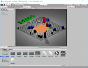
Set Up and Adjust the Scene in Unity
In Unity, we need to
- Import the position pass data (*.bin or *.txt) and store to a RGBFloat texture, to be used by the custom shader. In the demo, both are read in.
- Assign the pre-rendered background image to a quad and render with an (orthographic) Camera (CAM1). Adjust the camera so that it exactly renders the complete picture.
- Create a second ortho camera (CAM2), which renders after CAM1, has ‘Depth only’ clear flag and is positioned so that it looks at the origin the same way as the C4D camera did.**
- Add a 3D model as ‘test avatar’ and assign the custom shader to it (in my case, the model is a simple textured cube)
** This is a bit tricky. It might be best to export parts of the C4D scene and use as ‘check meshes’. Adjust CAM2 pos/rot/zoom until both, the imported check mesh and the pre-render picture from CAM1 are congruent. In my case, the C4D Camera was at pos 650/650/-650 cm, rot 45/-30/0 deg, zoom 0.238. CAM2 finally stood at pos 65/54.3/65, rot 30/315/0, zoom 16.1. The differences are probably caused by different world axes, zoom, import scale and some rocket science math that I don’t fully understand.
The Custom Depth Shader
The custom depth shader takes position information from the RGBFloat texture (formerly known as ‘the converted EXR file’) and calculates the distance of a background-pre-rendered pixel’s former world position (oh my) to the current camera (CAM2). It also calculates the distance of the current pixel in work (originating e.g. from our real 3D avatar) to CAM2. If the latter one is nearer than the ‘background pixel’, it will be drawn (discarded otherwise). This way, depth information of the C4D export is considered when drawing the scene as a combination of background picture and real 3D objects.
Shader "Unlit/TestShader1"
{
Properties
{
 _MainTex ("Object Texture", 2D) = "white" {}
 _PosTex  ("Position Texture", 2D) = "white" {}
 _minScale("Min Value for Scale", Float) = -100.0
 _maxScale("Max Value for Scale", Float) =  100.0
}

SubShader
{
 Tags { "RenderType"="Opaque" }

 Pass
 {
   CGPROGRAM
   #pragma target 3.0
   #pragma only_renderers d3d11
   #pragma enable_d3d11_debug_symbols
   #pragma vertex vertexShader
   #pragma fragment fragmentShader

   #include "UnityCG.cginc"

   struct VS_IN
   {
    float4 vertex : POSITION;
    float2 uv     : TEXCOORD0;
   };

   struct v2f
   {
    float4 vertex : SV_POSITION;  // clipspace pos
    float2 uv     : TEXCOORD0;    // uv coords
    float3 wpos   : TEXCOORD1;    // World pos
   };

   sampler2D _MainTex;
   sampler2D _PosTex;
   float4    _MainTex_ST;
   float4    _PosTex_ST;
   float4    _PosTex_TexelSize;
   float     _minScale;
   float     _maxScale;

   v2f vertexShader(VS_IN v)
   {
     v2f o;
     o.wpos   = mul(unity_ObjectToWorld, v.vertex).xyz; // World pos pixel
     o.vertex = mul(UNITY_MATRIX_MVP, v.vertex);        // Screen space pos pixel
     o.uv     = TRANSFORM_TEX(v.uv, _MainTex);
     return o;
   }

   fixed4 fragmentShader (v2f i) : SV_Target
   {
    // i.vertex: Pixel position in screen space (pixel value)
    // i.pos:    Pixel position in world space

    // _PosTex_TexelSize.zw is width, height of texture
    float2 bgUV = TRANSFORM_TEX((i.vertex.xy / _PosTex_TexelSize.zw), _PosTex);

    float fScaleRange = (_maxScale - _minScale);
    float4 C4DPosInfo = tex2D(_PosTex, bgUV) * fScaleRange + _minScale;

    float distC4D = distance(C4DPosInfo.rgb, float3(_WorldSpaceCameraPos.xyz));
    float distNow = distance(i.wpos, float3(_WorldSpaceCameraPos.xyz));

    float4 colObj = tex2D(_MainTex, i.uv);
    if (distNow > distC4D)  discard;
    //if (distNow > distC4D) colObj = float4(0.0, 1.0, 1.0, 1.0); For debugging

    return colObj;
 }
 ENDCG
 }
 }
}
Outlook
- The shader does not consider any lighting nor shadows. This could certainly be improved (somehow…).
- Currently, no camera movement or ‘maps’ larger than the current screen are considered. This might afford some more tweaking in the shader code. Also, CAM1 and CAM2 need to be ‘dynamically synced’ somehow then (not only one-time during scene setup).
Downloads
| File | Date | Size | Remarks |
| EXRShaderText_C4D_File.zip | 09/27/2016 | 1.8 MB | C4D scene, render and *.exr export file |
| EXRShaderTest_UnityDemo.unitypackage.zip | 09/27/2016 | 5.6 MB | unity demo (.unitypackage) |
| EXRShaderTestDemoProgram.zip | 10/08/2016 | 18.1 MB | unity demo (.exe) with pathfinding |
(The demo.exe: A red-colored swordsman in a mini dungeon)
